Design procedure of propeller shaftdesign of propeller shaft. A Procedure for Propeller Design by Inverse Methods by Richard Eppler and Martin Hepperle Institut A für Mechanik Universität Stuttgart Pfaffenwaldring 9 D-7000 Stuttgart 80 FRG Summary Two different inverse methods are applied to the design of.

Propeller Design Process An Overview Sciencedirect Topics
Methodicaldesign engineering is the heuristic use of newly developed and established methods within the engineering design process including theory-based and industry best practice strategic and tactical formalized and intuitive methods.
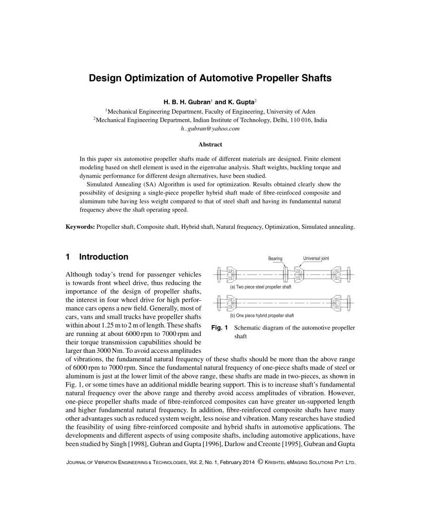
. Key word - propeller shaft composite material FEM analysis Design weight optimization etc. Conventional steel propeller shafts are usually manufactured in two pieces to increase the fundamental bending. In this paper six automotive propeller shafts made of different materials are designed.
This is to ensure enough gap between the shaftsenginesgearboxes for carrying out gap and sag alignment. Finite element modeling based on shell element is used in the. The propeller shaft exchanges motor torque to the back pivot through at least one widespread joint.
Shaft subjected to bending moment only. Design procedure flow chart for a shaft with fluctuating loading. Three forged schemes have been determined according to the shape of the forged and the conditions of the existing hydraulic presses in the factory.
Systematic and methodical procedures overlap but are not co-incident. The whole work can be divided in to the following steps. Shaft subjected to combined twisting moment and bending moment.
Vertical drive shaft 3. Determine the dimensions of the power transmitting devices and other components to. Based on design of shaft subjected to pure torsion from the theory of pure torsion we have Tr TJ J Polar moment of inertia d432 for a shaft of diameter d Taking a factor of safety FS 4 Max operating shear stress 4 25562 T maxFS D 16TT13 63095 16 803472 106 13 400037 mm Design of Propeller Shaft dp.
And brought down by the same amount thereby ensuring proper bearing contact at the bottom. The housing locates the bearings on their outer rings and receives. Features And Design Of Propeller Shaft Forging Process The main characteristics of propeller shafts forged are the large diameter of the flange and the length of the body.
Design and Optimization of Composite Propeller Shaft. The shaft is lifted with the pedestal bearing by 001 to 002 mm by reading on the dial gauge. Automotive propeller shaft is a very important component of vehicle.
DESIGN OF SHAFTS The shaft may be designed on the basis of 1. The main characteristics of propeller shafts forged are the large diameter of the flange and the length of the body. The splines on the finishes at the propeller shaft fit flawlessly into the splines in the sleeve.
It is used for power transmission from gear box to differential. Determine the shaft rotational speed. B Solution uses an integral pinion three shaft shoulders key and keyway and sleeve.
Determine the power or torque to be transmitted by the shaft. Propeller shaft material and the natural frequency of the thermoplastic polyimide with 30 carbon fiber is very closed to conventional material. Three forged schemes have been determined according to the shape of the forged and the conditions of the existing hydraulic presses in the factory.
Drive PDF IRJET- Design and Analysis of Propeller Shaft IRJET Journal - Academiaedu. Features And Design Of Propeller Shaft Forging Process. A Choose a shaft configuration to support and locate the two gears and two bearings.
The constraints on propeller design may take many forms. Rigidity and stiffness In designing shaft on the basis of strength the following cases may be consider 1. The propeller shaft is pushed back by about 5-6mm within the movement allowed by the seals prior to locking of the shaft.
Propeller shaft Stern Tube AZIMUTH THRUSTERS These thrusters can rotate full 360 degree with help of underwater gearbox which is driven by vertical power shaft. Shaft from Engine 2. Each places a restriction on the designer and in many cases if more than one constraint is imposed then this places a restriction on the upper bound of performance that can be achieved in any one area.
During this operation a dial gauge is kept on top of the shaft at 12 oclock position. The weight is optimizing up to the 8204 as compared to conventional propeller shaft material. Shafts subjected to twisting moment only.
A propeller shaft is an assembly of one or more tubular shaft connected by universal constant velocity or flexible joints. Once this is done the following are measured. Drive shaft is a mechanical component used to connect the drive train components which are not connected due to the distance between them.
Estimation of material properties. Carlton FREng in Marine Propellers and Propulsion Fourth Edition 2019 222 Design Constraints. Design Calculation We have designed propeller shaft for Automobile Therefore standard torque transmission capacity required for the most of the Automobile is 𝑇𝑝 610 Nm Outside diameter of propeller shaft for our design purpose 𝑑𝑜 100 𝑚𝑚 Length of the propeller shaft L 889 mm 41 Torsional Strength 𝜋 𝑇𝑝 𝜏 𝑑03 1 𝐾 4 32 Where 𝜏.
The number of tubular pieces and the joints depends on the distance between the gearbox and the axle. Propeller shaft with gear 4. COMPONENTS OF PROPELLER SHAFT.
In the present work aims to design and fabricate a propeller shaft made of composite material which could replace the conventionally available shaft. Features And Design Of Propeller Shaft Forging. CP propeller 7Hydraulic lines of CPP 8Oil fixed gearbox.

Propeller Design Process An Overview Sciencedirect Topics
Pdf Design Optimization Of Automotive Propeller Shafts

Propeller Design Process An Overview Sciencedirect Topics

Drive Shaft Design Calculation For Automobile

Pin On Places To Visit

An Introduction To Tunnel Thrusters In Ships Design And Application Introduction Complex Systems Ship

Propeller Shaft And Drive Shaft Automobile
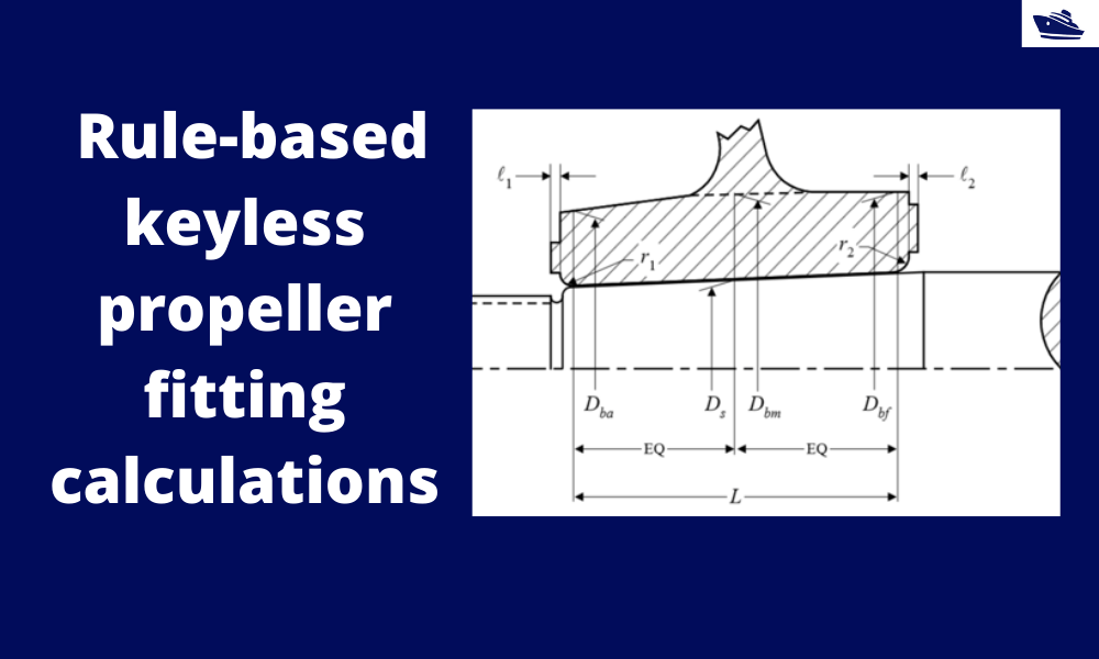
How To Do Rule Based Fitting Calculations Of A Keyless Propeller Thenavalarch
0 comments
Post a Comment